Transformations
Understanding Transformation Basics -
IMPORTANT INFORMATION
Transformations are the core of TagsCollector’s power. They can perform a multitude of functions and when properly implemented they will greatly reduce system development time, reduce entry errors, and eliminate repetitive data entry eliminate repetitive data entry. Therefore, understanding the information in this section is critical to the development of an effective SCADA system.
I. Introduction
A transformation is best described as a user defined set of instructions that transforms an input signal into one or more strategically formated output signals. Scaling analog values, assigning colors to the data, generating alarms, trimming unwanted decimal places, and an unlimited assortment of other functions are just a few examples of what transformations can do. Additionally, TagsCollector currently supports a total of three transformations per tag with each of the three transformations arranged in series, where the output of one transformation feeds the input of the next.
II. Creating a Transformation
However, for best explaining the concept, it is probably better to look at a simple example…
Say we have a group of 20 chemical storage tanks, each one receiving a signal from a 4-20mA sensor. The sensor produces a raw value of 4000 when the tank is full (10,000 gallons) and 20000 when the tank is empty (0 gallons). The PLC program doesn't currently contain a scaled value in it's database, but that doesn't matter since we can easily scale it inside TagsCollector without writing a single line of PLC code. Additionally, If the tank volume
To do this let's start by creating the transformation. selecting Edit > Transformation > Scale from the list of available options. This should produce an empty scale form and we will name this particular transformation “Tank Volume 10,000 Gal”
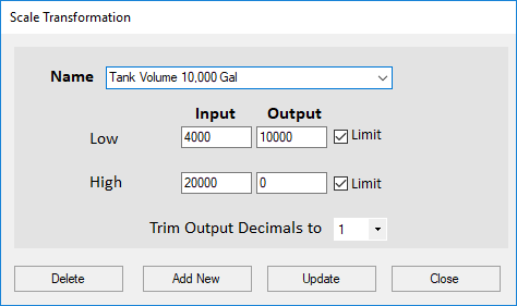
Next, simply enter the input values of 4000 and 20000 and the output values of 10,000 and 0, and then tell the transformation to limit the range to the min and max values so that the transformation always produces an output between 0 and 10,000. Additionally, we can trim unneeded decimal places and format the output of the transformation to display only one decimal place. Now just click the Add New button and the transformation is saved.
Next, let's select Edit > Transformation > Analog Offset Value from the dropdown list.
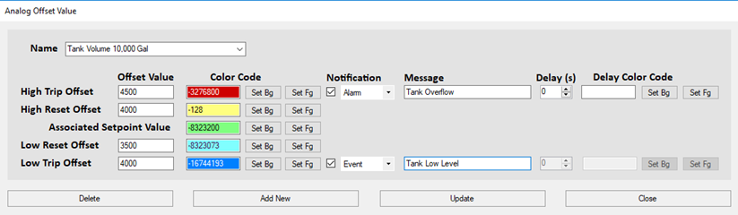
So, now if the PLC produces a raw value of 8324 then the scale routine transformation automatically converts that to an output value of 7297.5 gallons. However, we’re not done yet, because you can now take the output of this transformation and feed it into the input of yet another transformation. This time we will select something called an Analog Offset Value transformation.
Additional Alarm Functions
Alarm Checkbox: If the Alarm checkbox is checked for a particular transformation state, then the Alarm State for the tag will change if it reaches that state.
Alarm Message: The Alarm Message is a customizable message that is displayed as the Alarm State. If the text box is left blank, then a default message will be displayed.
Delay: The delay is the number of seconds that must pass before an alarm is triggered. For example, if the Alarm State is reached and the Delay is set to 60 seconds, the Tag will display Timing until 60 seconds goes by. If the state is still in the Alarm State after 60 seconds, the Alarm State for the tag will be updated and the Alarm will be displayed in the Alarm Manager. If the tag is not in the Alarm State after 60 seconds, then the alarm will not be triggered.
Delay Color Code: The delay color code is the background and foreground colors of the tag when it's Alarm Status is in a delayed or Timing state.
II. Transformation Overloading Wildcards
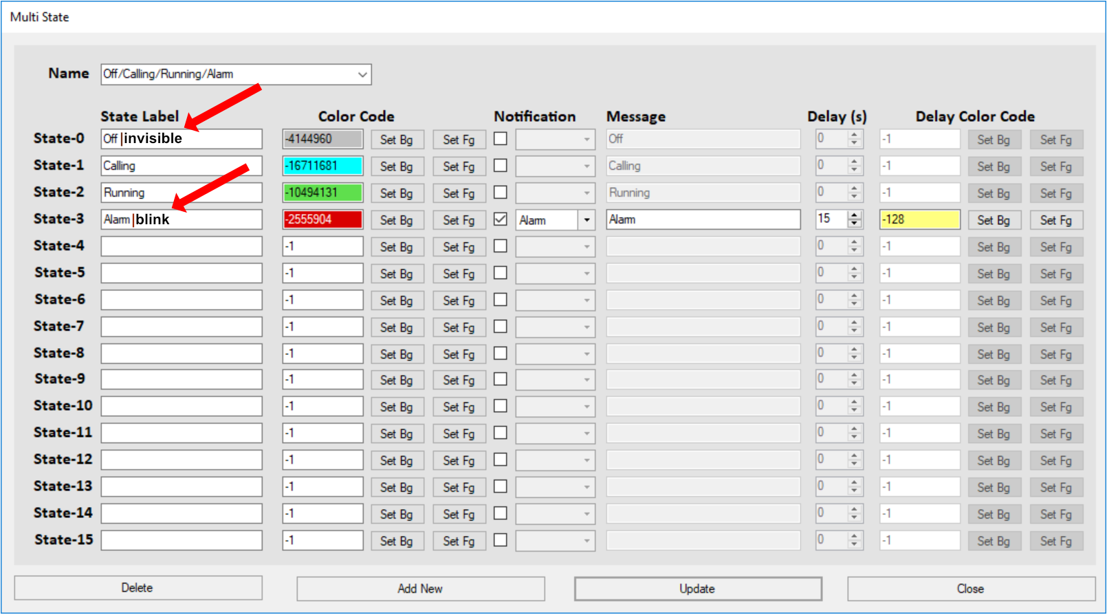
Many transformations that contain State Labels (e.g. Multi-State, Two-State, etc) can have also have additional actions or wildcards added to the label descriptor to further expand the transformation's functionality. This functionality is then passed over to the UI where it is utilized on the page displays.
Valid Wildcards are:
|blink
|bold
|invisible
|underline
Note that the "|" (pipe) character is used for separating the label from the wildcard.