Modbus
For Modbus TCP tags
- Open the TagsCollector Editor and select the Data Collection tab from the top of the page.
- In the data entry section at the bottom of the page, locate the Protocol drop down box in the Tag Type section and select Modbus TCP from the list of available options.
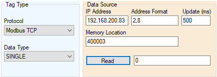
- Enter the IP address for the controller you would like to access
- Enter the Address Format that defines the type of tag addressing that is used in the controller. The configuration is defined as an X,Y value, where X is the Address Type (valid entries of 1-4)and Y is the Tag Type (valid entries of 1-10). See the tables below for configuration details.
e.g. If a tags address format is entered as 2,4 then the tag is expected to be a discrete input in the Modicon 6-digit format.
Address Type (X value)
|
Member |
Description |
|
1 - MODICON_5_DIGIT |
Indicates that the slave device uses the following register addressing format for the TagTypes shown: COIL: 1 to 9999 DISCRETE_INPUT: 10001 to 19999 INPUT_REGISTER: 30001 to 39999 HOLDING_REGISTER: 40001 to 49999 |
|
2 - MODICON_6_DIGIT |
Indicates that the slave device uses the following register addressing format for the TagTypes shown: COIL: 1 to 65536 DISCRETE_INPUT: 100001 to 165536 INPUT_REGISTER: 300001 to 365536 HOLDING_REGISTER: 400001 to 465536 |
|
3 - ONE_BASED |
Indicates that the slave device uses the following register addressing format for the TagTypes shown: COIL: 1 to 65536 DISCRETE_INPUT: 1 to 65536 INPUT_REGISTER: 1 to 65536 HOLDING_REGISTER: 1 to 65536 |
|
4 - ZERO_BASED |
Indicates that the slave device uses the following register addressing format for the TagTypes shown: COIL: 0 to 65535 DISCRETE_INPUT: 0 to 65535 INPUT_REGISTER: 0 to 65535 HOLDING_REGISTER: 0 to 65535 |
Tag Type (Y value)
|
Member |
Description |
|
1 - COIL |
Indicates that the Item represents a COIL type on the hardware device. Coil are discrete data points with BOOLEAN values. |
|
2 - COMM_EVENT_COUNTER |
Indicates that the Item represents the data values returned from the Modbus Get Comm Event Counter function (function code 11). Get Comm Event Counter data consists of a 16-bit status word and 16-bit event counter. Get Comm Event Counter is read only. |
|
3 - COMM_EVENT_LOG |
Indicates that the Item represents the data values returned from the Modbus Get Comm Event Log function (function code 12). Get Comm Event Log data consists of a 16-bit status word, 16-bit event counter, 16-bit message counter, and 0-64 bytes of events. Get Comm Event Log is read only. |
|
4 - DISCRETE_INPUT |
Indicates that the Item represents a DISCRETE INPUT type on the hardware device. Discrete inputs are discrete data points with BOOLEAN values. Discrete inputs are read only. |
|
5 - EXCEPTION_STATUS |
Indicates that the Item represents the data values returned from the Modbus Exception Status function (function code 7). Exception Status data consists of eight Exception Status outputs (bits) packed into a single byte. Exception Status is read only. |
|
6 - FIFO_QUEUE |
Indicates that the Item represents the data values returned from the Modbus Read FIFO Queue function (function code 24). Read FIFO Queue data consists of a series of a 16-bit FIFO Count field, and up to 32 FIFO register 16-bit values. FIFO Queue is read only. |
|
7 - FILE_RECORD |
Indicates that the Item represents a file record type on the hardware device. A file is an organization of records. Each file can contain up to 10000 records addressed 0 to 9999. File records are analog values stored in 16-bit registers. Multiple 16-bit registers can be combined to create 32-bit and string types. File records are accessed using Modbus File Record Read function (function code 20) and File Record Write function (function code 21). |
|
8 - HOLDING_REGISTER |
Indicates that the Item represents a HOLDING REGISTER type on the hardware device. Holding registers are analog values stored in 16-bit registers. Multiple 16-bit registers can be combined to create 32-bit and string types. See HWDataType Property for additional information. |
|
9 - INPUT_REGISTER |
Indicates that the Item represents an INPUT REGISTER type on the hardware device. Input registers are analog values stored in 16-bit registers. Multiple 16-bit registers can be combined to create 32-bit and string types. See HWDataType Property for additional information. Input registers are read only. |
|
10 - SLAVE_ID |
Indicates that the Item represents the data values returned from the Modbus Report Slave ID function (function code 17). Report Slave ID data consists of a series of bytes that represent the slave device's ID. Number of bytes in Slave ID is device dependent. Slave ID is read only. |
- Next, enter the Memory Location in the numerical addressing format as dictated in the below addressing format. E.g. 10001, 400004, etc.
- Select the Data Type of the tag added that matches the data type in the PLC.
Data Types
|
Member |
Description |
|
BCD16 |
16-bit BCD integer. Can be stored in a single Modbus register. |
|
BCD32 |
32-bit BCD integer. Occupies two contiguous registers on the hardware device. |
|
Int16 |
16-bit signed integer. Can be stored in a single Modbus register. |
|
Int32 |
32-bit signed integer. Occupies two contiguous registers on the hardware device. |
|
Single |
32-bit floating point. Occupies two contiguous registers on the hardware device. |
|
String |
Variable length string. Each Modbus register can store two packed characters. |
|
UInt16 |
16-bit unsigned integer. Can be stored in a single Modbus register. |
|
UInt32 |
32-bit unsigned integer. Occupies two contiguous registers on the hardware device. |
- Enter an Update time that is desired for the tag. See the Tag Update Time section for additional help in selecting optimum update times while reducing system overhead.
- Once the tag name has been entered, click the Read button to verify operation and see the current value of the tag.